 You
can perform diagnostics on an adapter only when no other program is using
the adapter.
You
can perform diagnostics on an adapter only when no other program is using
the adapter.Run the hardware diagnostics immediately after you install the hardware to verify that you correctly installed the CHANNEL-OUT adapter and cable and that they function properly. Thereafter, you can perform the diagnostics whenever you want to confirm that the hardware functions properly.
The test transfers data to and from the adapter and compares the data to make sure the adapter is working. When you install the test plugs, the diagnostics test raises signals and expects the signals to be looped back.
Complete the following steps to verify that you correctly installed the CHANNEL-OUT adapter and cable and that they function properly.
You
can perform diagnostics on an adapter only when no other program is using
the adapter.
Phase 1 confirms that all connections are valid, the adapter drivers are valid, and the adapter and its components are working. The software locates the adapter and performs an internal adapter test.
Complete the following steps to run Phase 1.
Stop all programs or services using the CHANNEL-OUT device driver.
Connect the adapter test plug to the adapter. Adapter test plugs can only be used with Revision 3 or later adapters.
Open the BARR/CHANNEL-OUT utility.
From the Diagnostics tab, select the device to test and then click Start.
As the test runs, diagnostic status messages display. Review adapter test errors, if any.

Phase 2 confirms that the cable is working. The software verifies correct functioning of the cable by sending a data string through the adapter in a rotating pattern. The adapter test plug returns the data through the receive-side of the adapter. The test verifies that the returned data matches the sent data.
Complete the following steps to run Phase 2.
Stop all programs or services using the CHANNEL-OUT device driver.
Connect the adapter cable to the adapter.
Attach the test plug(s) to the other end of the cable.
Open the BARR/CHANNEL-OUT utility.
From the Diagnostics tab, select the device to test, and then click Start.
As the test runs, diagnostic status messages display. Review adapter test errors, if any.
If this test passes but you still suspect a malfunction
in the printer chain, test
the entire printer chain.
To test the adapter and CHANNEL-OUT cable,
install the test plugs on the CHANNEL-OUT cable.
Perform this test if the adapter and CHANNEL-OUT cable test passes but you still suspect a malfunction in the printer chain. This test is the same as the adapter and CHANNEL-OUT cable test, except that you install the test plugs on printers or daisy-chain (1) A set of devices (such as printers) connected in series. (2) To connect a series of devices, one to another, like daisies in a chain of flowers. cables instead of on the CHANNEL-OUT cable.
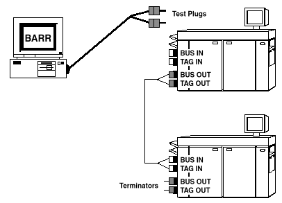
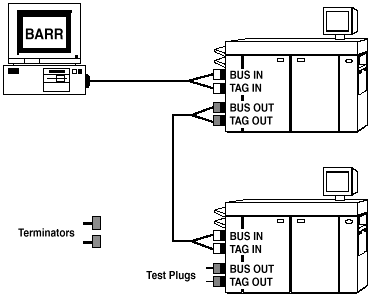
First, test the entire printer chain. If the test reports an error, you can systematically rule out problems with each cable or printer by running the test several more times, each time with the test plugs attached to the next cable or printer in the chain. Complete the following steps to test the printer connectors In hardware, couplers used to join cables or to join cables to devices. and daisy-chain cables. The following diagram shows how to connect the cables and test plugs.
Stop all programs or services using the CHANNEL-OUT device driver.
Power off all printers. The test is not accurate if the printers are turned on.
Cut the test plugs from the end of the CHANNEL-OUT cable. Be careful not to misplace the test plugs because you might need them later. You might want to re-attach the test plugs to the cable when you finish testing.
Re-attach the CHANNEL-OUT cable to the first printer’s Bus In and Tag In connectors.
Remove the terminator plugs Parts that end the cable paths on computer systems. The terminator plug is attached to the last device in a series. from the last printer.
Install the test plugs on the last printer’s Bus Out and Tag Out connectors.
Open the BARR/CHANNEL-OUT utility.
From the Diagnostics tab, select the device to test, and then click Start.
As the test runs, diagnostic status messages display. Review adapter test errors, if any.
If
the test passes, all of the hardware components are functioning properly.
If the test fails, refer to the Isolating
the error topic.
To test the entire printer chain, install
the test plugs on the last printer.